Hello

There is a very large class of people that own 65/66 Mustangs that, as far as I can tell, anyway, have been, for the most part, ignored entirely. They don't really want that 100 pt. show car that is so nice and was soooo expensive that they're afraid to drive it, they also don't want to make their car capable of achieving warp factor three. They just want this car that they dearly love to be able to cruise around smoothly and reliably, without having it dump them out on the side of the road or have it start making weird noises or belching out big clouds of funky-smelling smoke. And I think, truth be told, that this is by far the largest class of Mustang owners. They take their car to some technician when what they actually need is a mechanic, and this, frequently, does not work out very well at all for the owner. They don't want to re-engineer the entire car, they just want someone to fix what broke. These are the people that I am trying help out with this blog. Some problems require a little bit of back and forth, as in, "Try this." "I tried that and it didn't change anything."
" Oh. well, you probably need to try that." " I tried that and it helped, but it still isn't quite right." "Now you need to try this...." If you go to http://www.allfordmustangs.com/ and then go to the classics forums, you will be able to do that with a pretty hefty gathering of some very knowledgeable people that also happen to be very friendly. None of that ridiculous one-upmanship, no flaming or abuse, none of that stuff. Just good, solid advice from people that know what they are talking about.

Monday, March 31, 2008

Mustang gauges 1965 and 1966


This is the wiring diagram for the gauges on a 66 or a 65 that has either the GT (Performance/ Image Option) package or the Interior Decor Group, a.k.a. Pony Interior. If you click on the diagram, you will be able to see all of it, instead of just the left side. What I'm dealing with here will just be the water temp, fuel and oil pressure gauges. The ammeter gauge is a free-standing, independent system that has absolutely nothing to do with the other three gauges. The gauges on your car make up a system that supplies you with some very useful information when it is working correctly, and is a very simple system to understand and repair. What you have is a black wire with a green stripe on it coming from the back of the ignition switch going to the instrument cluster voltage regulator. The ICVR takes the 12V from the switch and, by means of thermally actuated contact points, knocks the voltage down to about 6 volts. The reason that Ford did it like this was because they had all of these perfectly good gauges of a proven level of reliability that were originally intended for a car with a 6V electrical system, and, rather than redesign and manufacture all new stuff, they just used a voltage regulator in the system. Ok, now that we have gotten that out of the way, you still have that black wire with the green stripe going from the ignition switch to the ICVR. On the other end of the ICVR you have a wire, still black/green that splits off to the three gauges. That wire plugs onto the what is the driver's side of the gauges when they are mounted in the dash. This wire brings power to the gauges. On the fuel gauge there will be a yellow wire with a white stripe that goes to the fuel sending unit in the gas tank. On the water temp gauge there will be a red wire with a white stripe that goes to the water temp sending unit, located towards the front of the intake manifold on a V8 and towards the rear of the cylinder head on a 6cyl. There will be a white wire with a red stripe going to the oil pressure sending unit, down near the oil filter. The wires going to the sending units work as a ground, with the sending unit itself determining how 'good' of a ground the gauge is getting.
If all three gauges are acting stupid on you, the problem is either the ICVR or the wire bringing the power to it. There is a dash to chassis ground wire that is hooked to the mounting screw of the ICVR, but that is what makes your dash lights and stuff go goofy on you. It doesn't have anything to do with the gauges.
If one or two of the gauges seem to be functioning normally and only one or two of them is having trouble, then the problem is almost always either the sending unit, the wire going to the sending unit, or the wire going from the ICVR to the gauge. Once in a blue moon it will actually be the gauge itself, but that happens so seldom that it really isn't even worth mentioning.
If the gas gauge is the one acting goofy the first thing that you want to do is to unplug the wire from the sending unit and, with the key in the 'On' position, ground that wire out to a suitable place on the car that isn't insulated from the rest of the car. The leaf spring shackles, for example, are in a handy location, but are completely insulated by the bushings. If the gauge pegs to full, the problem is inside the tank. The problem inside the tank is, far more often than not, the float isn't floating anymore. The brass floats cost like 5 bucks, whereas, a Ford sending unit costs nearly two hundred, and the repops cost about fifty and normally don't work. If the gauge does not peg to full, then the problem is either the wire going to the sending unit or the wire coming from the ICVR to the gauge.
If the water temp gauge is the one acting funny, again, ground the wire out somewhere and see if the gauge pegs. If yes, replace the sending unit. They also are cheap. If no, it's probably the wire going to the sending unit. People have the annoying tendency to cut that wire and then strip back both ends and tie the two ends back together. Don't do that. A brand new engine gauge feed only costs about twenty bucks, and you'll have brand new stuff that will work reliably for many years to come. If money's a bit tight, use some proper connectors of the male/female plug-in variety and wrap that to insulate it. All of what I just said about the water temp gauge is also true about the oil pressure gauge.
This isn't complicated. You can do this, and you can do it right.


Sunday, March 30, 2008

Setting the points in your distributor


Contrary to popular opinion, setting the points in your distributor is not a dark art. It is actually a very simple procedure. In the picture on the bottom, the point gap, circled in red, is closed and there is a yellow arrow pointing at one of the 8 ( or 6 on 6 cyl car) distributor cam lobes. In the picture on the top, the points are open and the point gap is indicated by the yellow arrow. After removing the distributor cap and rotor, and then installing the new points, rotate the crank shaft in a clockwise direction from facing the motor with a 15/16 socket wrench on the big bolt in the middle of the crank shaft pulley until one of the bumps on the distributor cam is holding the points all the way open. If the points don't seem to open at all when you rotate the crank, loosen the screws and move the points in closer to the middle of the distributor, so that, as the distributor turns, the points open and close.. With the two mounting screws loose enough to slide the points back and forth, move the points to the place where the gap is correct. On a 6 cyl car the point gap should be .024-.026 inches, on a 260 or a non-hipo 289 the point gap should be .014-.016 inches and on a hipo 289, or K code, the point gap should be .019-.021 inches. Then tighten up the two mounting screws. A hipo 289, the K code, is supposed to have a dual point distributor. On these, you do what you just did twice, as there are two sets of points in there instead of just one. The reason that the hipos got this type of distributor was because the motor was designed to run at much, much higher RPMs than the other motors, and in extremely high RPM situations, something called 'point float' can occur. That's when the points don't really close quite right and sort of hang around the outside area of their travel and flutter. Having two sets of points greatly reduces the frequency and severity of this happening.
Breaker point ignition systems have fallen into ill-favor in most circles, but personally, I don't think that they deserve this. A whole bunch of cars kept chugging down the road for a whole bunch of years running on breaker points. I have a pertronix unit in the distributor of my car, because they function consistantly until the day that they fail entirely, kind of like a light bulb, but I also keep a set of points and condensor in the glove box of my car, because that is something that I know for sure will work, and is a very simple swap, in case I have to do that on the side of the road.

Just a quick update. I now have the points back in the distributor instead of the pertronix. I got tired of having something in my car that I didn't understand and, consequently, didn't trust.

Date codes


Ford used a few different formats of date coding the parts on a 65/66 Mustang. On sheet metal parts, such as fenders, hoods, shock towers, etc... there will be a number that goes like 4 12 2D. The first number is the month, with this one being, as you might suspect, April. The next number is the day of the month. The next one is the shift that stamped this particular part, in this case the second shift, and the letter indicates the plant that produced this particular part. The D is Dearborn, MI. C would be Cleveland, OH. W is Windsor, Ontario. There is nothing to indicate the year on the sheet metal parts. The picture is from the floor of my car underneath the back seat and this part was stamped on May 21st on the 3rd shift in Cleveland.


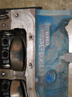
On cast iron parts, like cylinder heads, engine blocks, etc.. the format is different. They go like 4M13. The first number is the last digit of the year, the letter is the month and the next one or two digits are the day of the month. The picture of the engine block shows a date code of 5L20, which is november 20th of 65. The picture of the cylinder head shows a date code of 9A9, which is January 9th of 69. On the letter designations a lot of people 'miscount' because they didn't realize that Ford did not use the letter I (eye) because it looks too much like the number 1.


The aluminium parts, like bell housings, some water pumps, etc.. Had a system that is a little bit weird looking if you are unfamiliar with how it works, but is actually pretty simple. There will be a two digit number, indicating the year, inside a circle that has some bumps around the perimeter. On a really, really nice one, it looks like a pie sliced into 12 pieces, but most parts haven't withstood the march of time nearly well enough to be able to see that. On this picture of the starter hump on a five-bolt bell housing, you will see the number 64, indicating, as you might suspect, 1964, and 4 little bumps. That means April, so this bell housing was cast in April of 1964.

Nothing to it.


The date codes used for the scheduled production dates of cars was simply a two digit number, indicating day and a letter indicating month. There is sometimes a little bit of confusion surrounding the letter designations for the 65 model production year. The sheduled production date of the first Mustangs were in march of 64, so the letters A and B weren't used then. They started with C for march of 64, going C-H for march through august of 64, skipping the letter I and using the letter J for september and going J-M september through december, jumped back to the letter A for january of 65, B for february of 65 and picked back up with Q for march of 65, and went Q-V for march-august of 65.

The carburetor tag will have a date code stamped on it which will have 3 digits, one number followed by two letters. The number is the year, followed by the month and then the week of that month. The one in the picture says 6CC, which would be 1966, march, the third week of the month. Sometimes you will see the letter 'E' as the last digit on the tag, which is the fifth week of the month. If the first falls on a friday, production for that month would have fallen across five different weeks.
The distributor date code is in the same format as the cast iron parts, except for it is stamped into the housing, instead of cast in, like on an engine block or cylinder head or something.


Saturday, March 29, 2008

1965 Mustang wiring diagrams


1966 Mustang wiring diagrams


Fog light wiring


Here is how you hook up the fog lights under the dash so that they will A) work like they're supposed to, and, B) not set your car on fire. The picture at top is the end of the tail light harness that is under the dash. The two prong connector is the rear turn signals and it is plugged into something that comes out of the steering column, near the rest of the wires that come out of the steering column for the turn signal switch. The three prong connect is plugged into a matching three prong connector that is part of the under dash harness. Unplug those two connectors in your car and plug in the two three-prong connectors of the fog light under dash harness ( middle picture) with the connector circled in red on the tail light feed plugged into the connector circled in green and indicated by the two yellow arrows in the picture of the fog light underdash harness. Plug the other connector circled in green into the three prong connector in the car's main underdash harness that is still just flapping in the breeze up there. The connector circled in red on the fog light harness plugs into the connector on the fog light switch. The long grey wire goes out through the firewall and the blue wire with the black stripe is attached to a little circuit breaker. The other prong of the circuit breaker has a wire ( supplied by you) that is attached to the back side of the ignition switch. On a real-live, factory GT, (which was what the fog lights came on) that circuit breaker would have been mounted on the big bracket that the pedals are hanging from. It needs to be mounted somewhere, though, and insulated, so that it isn't bouncing around, shorting itself out on stuff as you go down the road. Most folks mount it to the pedal bracket and wrap it up with some electrical tape.


1965 and 1966 Mustang horn wiring and troubleshooting


Here is how your horns are supposed to be. The first diagram is the 64 1/2 horns, which have a horn relay and only one wire for a contact in the turn signal switch. I'll talk about those in a later post. Right now you can only see part of the wiring diagrams, but, if you click on one of them, the rest of it will show up.  The rest of this is post is for the 65/66 cars that have an alternator instead of a generator.

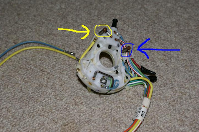
The first picture is the wiring of everything horn-related that isn't right behind the steering wheel. The last picture is a new turn signal switch. This one is the switch for a 68. I used it because the only new switches that I could easily find were all 68s, but the part concerning the horns is the same as a 65/66. The arrows are pointing to the horn contacts in the switch. The one with the yellow arrow is the one supplying power to the horns and the one with the blue arrow is the one that takes the power from the switch out to the horns themselves. The third picture is the back of a steering wheel. This is an 85 crown vic steering wheel, but, again, the horn stuff is the same. One of the horn contacts on the turn signal switch is making contact with one of the copper rings on the steering wheel, and the other horn contact touches the other ring. On the front of the steering wheel, with the three-legged horn button removed, you will see a little metal 'finger' sticking out. That is in contact with one of the copper rings on the back of the steering wheel on the back and is in contact with the metal ring on the three-legged horn button. You will also see two contacts, each made of white plastic with a little copper contact on the front of the steering wheel, held onto the wheel with a screw. In this picture of the back of the three-legged horn button I have circled two contacts on it. When you push on the horn button, that causes one, or both, of the contacts on the horn button to touch the contacts on the steering wheel, completing the circuit and causing the horns to honk.
It is a very common problem for the contacts on either the steering wheel or the horn button to be worn down enough to either make very poor contact or no contact at all. To get your horns to work, first check and see if the horns themselves work by removing one, grounding the mounting bracket on the negative battery post and supply power to the connector on the horn with a wire from the positive battery post. If the horns work, check with your volt meter to see if power is getting to the horn end of the wire that is supposed to be supplying power to the horn with the button pushed. If yes, then the horns aren't making good contact with the radiator core support because of excess paint or something. If no power is getting there with the horn button pushed, you'll need to remove the horn button by pressing and turning the horn button counter-clockwise and it will pop off of the steering wheel. Take a little wire or the trusty screwdriver or something and ground one of the contacts on the steering wheel to that little finger sticking out. If that makes the horns honk, the problem is the contacts on the back of the horn button. If no, then you have to remove the steering wheel. Once you've accomplished that, take the screwdriver and and ground one of the contacts on the turn signal switch to the other one and see if the horns honk. If yes, then the steering wheel was not making contact with the turn signal switch contacts and when you reinstall the steering wheel, you need to make sure that it gets pulled down far enough to make contact by checking to see if the horns honk by grounding one of the contacts on the front of the steering wheel to that little finger. If no, then the yellow wire probably isn't supplying power to the system at all and you need to first check if the yellow wire is bringing power from the headlight switch. If yes, you'll be needing a new turn signal switch.


Turn signals


Here is the wiring diagram for just the turn signals. How they work is power comes from the ignition switch to the signal flasher. From the signal flasher it goes into the turn signal switch and from there to the appropriate stuff on the left or right-hand side of the car. On a 66, or a 65 with the GT package, or pony interior, if only one indicator isn't working, like the left dash indicator for example, that is normally the bulb is burned out. Sometimes it will be a socket or a wire problem, but normally the bulb itself. On a 65, there is only one dash indicator light for both turn signals. That bulb has two wires going to it, instead of only one, like a 66. If an entire side isn't working, that will normally be a turn signal switch problem. If nothing works at all, start at the signal flasher to make sure power is both getting there and leaving there. If yes, you probably have a break of some sort in the wire that goes from the flasher to the turn signal switch. If the appropriate lights come on, but just don't flash, that is a bad flasher. Your car uses the flasher with the part number of 552, and is available at any auto parts store for nearly nothing.

Friday, March 28, 2008

Electrical problem diagnosis

Hello. The electrical problems that your car might experience are generally not very complicated. The first step in figuring out how to fix the problem is to determine if there even is a problem. That might sound a bit odd, but I have seen many, many occassions in which someone was trying to fix a problem that didn't exist, so, first, find out if the car is supposed to be ' doing that' or not. The only tool that you will need, other than basic hand tools, will be a volt meter of some sort. Electrons flow, for all practical purposes, just like water. They need a place to come from, they need a place to go, and they need an unbroken path between those two places. Once you have determined that there is a problem with a particular system, you start at the battery and check with your volt meter for power all the way along the circuit until you find the kink in the flow. On electrical systems, the ground is the ' place to go'. A faulty ground connection can make electrical systems do all sorts of weird things, just bear in mind that extreme symptoms don't always indicate an extreme problem. Normally, on these cars, electrical problems result from either a failed component, like a signal flasher or voltage regulator, a ground connection that has gotten all corroded and funky-looking or a wire that has corroded or broken. You simply start at one end of the system and go through until you find the culprit. Intermittent problems, like headlights blinking out at bad times, are normally, but not always, the result of an ancient switch that just needs to be replaced. If jiggling something seems to be making something get better ( or worse) then whatever it is that you are jiggling is probably either the actual problem area or is attached to the problem area. It isn't rocket science on these cars. You can do this.