Sunday, April 27, 2008

Optional equipment for the Mustang

Here are the available options, along with their part numbers, and how much they would have cost 'back in the day'. These were the prices in June of 1966. You can see slight variations in the prices in different Ford publications printed at different times. The old 'Prices are subject to change without notice' thing.


Television---------------------------------C5AZ-18804-A----------$169.95


Deluxe 14" wheel cover w/spinner---------C6ZZ-1130-B-------------$33.20 (set of 4)


'Mag' wheel cover/14"---------------------C6OZ-1130-J-------------$81.15 (set of 4)


Styled steel wheel-------------------------C5ZZ-1007-B(wheel)------$158.40(set of 4)


Lug nuts----------------------------------C5ZZ-1012-A-------------$9.60(set of 20)


Center cap--------------------------------C5ZZ-1130-G-------------$10.00


Wire wheel cover-------------------------C5OZ-1130-C--------------$83.35(set of 4)


'White wall' trim rings 13"-----------------C5AZ-1211-A--------------$14.58(set of 4)


14"-----------------C5AZ-1211-B---------------"-------------"


15"-----------------C5AZ-1211-C---------------"-------------"


Floor mats/ front twin---------------------C5ZZ-6513086*-----------$7.95


/ Rear twin---------------------C5ZZ-6513106*------------$4.96


*= specify color


Full Tonneau Cover( cockpit cover)--------C5ZZ-76501A42-A(blk)---$52.70


"---------------------------------)--------C5ZZ-76501A42-B(wht)---$52.70

Door edge guards-------------------------C5ZZ-6520910-A----------$3.45

Rear seat armrest with ashtray-----------C5ZZ-6531600------------$15.20 pr (65)

"------------------------------"----------C6ZZ-6531600-------------$15.20 pr (66)

Air conditioner---------------------------C6ZZ-19700-A(6 cyl)-B(V8)-$240.00

Speed control----------------------------C6AZ-9A818-A--------------$71.40

Throttle control kit----------------------C4AZ-9B742-A--------------$10.00

Engine coolant heater------ 550 watt----C3RZ-8B152-A--------------$13.45

"--------------------------"1000 watt--C3RZ-8B152-B--------------$15.50

Both plug into household outlet

Power brakes----------------------------C62A091-A-----------------$47.00

Inside day/night mirror-----------------C6ZZ-17700-A--------------$4.95


Right-hand standard mirror------------C3RZ-17696-A---------------$2.45

Left-hand remote mirror---------------C5ZZ-17696-A---------------$12.95

Cigarette lighter/ map light------------C2RZ-15072-A---------------$3.00

Trunk light----------------------------C2RZ-15A700----------------$2.35

Parking brake warning light----------C4DZ-15A852-A---------------$3.80

Spot light----------------------------C5ZZ-15313-A(L.H.)-----------$29.95

"---------"--------------------------C5ZZ-15313-B(R.H.)------------$29.95

Turn signal-Fender mount----------C5AZ-13A310-A----------------$7.15 pr

Compass----------------------------C4RZ-19A548-A----------------$7.95

Trunk mount luggage rack----------C5ZZ-6555100-F---------------$39.95

Luggage rack hold-down straps-----C5ZZ-6555196-A---------------$5.25

Electric clock-----------------------C6ZZ-15A000-A----------------$20.80

Vinyl top--------------------------C5ZZ-6350005-A(blk)-B (wht)--$69.50

Stainless sill plate-----------------C5ZZ-6513242-A----------------$9.95 pr

Litter basket---------------------C1AZ-19D504-A thru D----------$2.45

Tissue dispenser------------------C3RZ-19A549-A----------------$3.95

Remote trunk release-------------C6AZ-65432A00-A------------$6.95

Adjustable clothes rod-----------C4AZ-19D536-A-----------------$3.00

Auto vacuum (plugs into lighter socket) C5AZ-19E521-A----------$14.95

Radiator bug screen-------------C5AZ-8198-A-------------------$1.95

Am/Fm radio-------------------C6ZZ-18805-BA----------------$123.15

CB radio------------------------C5AZ-18805-E------------------$179.50

Two-way walkie-talkie---------C5AZ-18805-F------------------$119.50

Studiosonic sound (reverb)-----C6AZ-18875-A------------------$27.95

Luggage rack zipper bag-------B9AZ-19B507-B-----------------$39.95

Rotunda child car seat---------C6AZ-19E535-A-----------------$29.95

Rotunda child safety vest------C6AZ-19F519-A-----------------$10.95

Child proof lock knobs--------C6AZ-5421850-A-----------------$2.95 pr

Reflector/ flare kit-----------C5AZ-19E500-A-------------------$11.20

Fire extinguisher/ 2 3/4 lb--C3RZ-19B540-A-------------------$16.50

"-----------------" 5 lb------C5AZ-19B540-A------------------$27.50

Dual air horns---------------C5AZ-13800-A-------------------$53.50

Glove box lock--------------C4DZ-6206081-A-----------------$2.50

Engine gauge kit------------C6AZ-10B944-B-------------------$45.00 ( A single round gauge housing with engine vacuum, water temp, oil pressure and volts. Not the rally-pac)

Cobra Tach------------------C5AZ-17A326-A (6K, V8) (-B 6k, 6 cyl) $42.50

Cobra tach------------------C5AZ-17A326-C ( 9K, V8)---------$46.50

Sun Tach-------------------C4AZ-17368-A (9K V8)-----------$60.00

Sun Tach mounting kit------C4AZ-17368-A-------------------$6.10

Seat belt retractors---------C4AZ-62611A06-A---------------$3.85 pr

I'll put some more of this stuff up later, when I type it up.

Wednesday, April 23, 2008

Carburetor common repairs and adjustments

This first picture is of the accelerator pump diaphragm housing, held onto the front of the carb with four screws.If fuel seems to be leaking from that hole towards the bottom of it, that means that the diaphragm is ruptured and needs to be replaced. The ruptured diaphragm will also make the car behave very badly coming from a dead stop. First, you remove the four screws and pop the housing cover off and swing it out of the way. What you will see when you do that is shown in the sixth picture. That is the diaphragm itself. Pull that thing off. When you do that, what you will see is in the fifth picture. That spring is what pushes the diaphragm back outafter the arm cam pushes it in. If this is all that you intend to do to the carb, just put the new diaphragm on, making sure that it goes on facing in the same direction as shown in the picture, with the spring underneath it, replace the cover, snug up the screws and you're good to go. Do not overtighten the screws because you could strip out the screw holes and the carb will leak like crazy from that day forth.


If fuel is gushing out of the vent tubes on the top of the carb, that means that your needle and seat assembly is not working correctly. This is commonly called ' float is stuck'. To replace the needle and seat assembly, remove the top of the carburetor by first removing the little clip holding the choke flap arm onto the choke linkage. It is shown (sort of) in the third picture. It is that tiny little clip just to the left of the dirty brown plastic thingy. Next, remove the four screws from the top of the carb, along with the stud that holds the breather assembly wing nut on and remove the top of the carburetor. What you will see is shown in picture #11. In picture #10 you see the float clip popped loose. pop the clip loose on yours and lif the float out of the carb. There will be a little brass thingy with a rubber tip hanging on the end of it, as shown in picture #9. You will then remove the brass seat that is screwed into the carburetor, shown in picture #8. Use a 6 point 3/8 socket wrench for this. When you install the new one, be sure to put the new gasket underneath the seat assembly. Replace the old needle ( brass thingy with rubber tip) , reinstall the float with the needle inside the seat, without dinging it up, reattach the clip holding the float in, and again, you are good to go.


If, when you remove the top of the carburetor, yours is all funky and crusty-looking, like the one shown in picture #7, you need to clean that stuff up before you put the carb back together. Those two brass things that look like screw heads with a hole in the middle of them are your main jets. You remove them with, that's right, you guessed it, a big flat blade screwdriver. That other thing in there with the brass tip is the top side of your power valve. This is replaced by flipping the carb over, assuming that you've emptied the fuel out of the carb by now, and removing the housing cover, as shown in picture #15, by removing the four screws and popping it off of there. What you will see is shown in picture #14. That is the other end of the power valve. It unscrews in the normal way with a 1 inch open-end wrench. Unscrew it and install the new one, again, making sure that you also replace the gasket underneath it, then replace the cover, again, with the new gasket, and that is that.
Autolite carbs, with the exception of the K code 4bbls, have thermostatically actuated chokes. How the choke is adjusted is by loosening the three screws on the choke thermostat housing, which is the round black plastic thing on the passenger side of the carb, shown in picture #3, and rotating it slightly, then tightening up the screws. You will notice that there is an indexing mark on the carb to help you keep track of the adjustments you make. Rotating the housing clockwise makes the choke open sooner, counter-clockwise makes the choke open later.

The idle speed is adjusted by running the screw on the throttle linkage on the driver's side of the carb, as shown on the right hand side of picture #12. The fast(cold) idle speed is adjusted by the screw on the choke linkage over on the passenger side of the carb shown kind of right in the middle of picture #14. Nothing to it.


Basic carburetor function

Here's how your Autolite 2100 or 4100 carburetor does what it does. Understanding this is essential to diagnosing and correcting any problems that it might be having. The carb is responsible for delivering fuel to the engine. How it does this is by a couple of basic physical principles. One is that air moving through an hourglass shaped tube is at it's highest velocity and lowest pressure at the skinny part of the tube. This was discovered by an Italian physist named, that's right, you guessed it, Giovanni Battista Venturi. Your carburetor's fuel bowl has a vent hole on top of it. The pressure at the top of the fuel is normal atmospheric pressure because of the vent hole. The fuel has a few different routes that it can take to get into the venturis, but at the discharge port, the air pressure is lower, because of the venturi effect, than it is at the top of the fuel bowl. That creates a 'push' on the topside of the fuel. An Autolite carb has three basic fuel circuits. One is the idle circuit. This is the path that the fuel follows when the throttle plates at the bottom of the venturis are closed. The discharge ports for the idle circuit are below the throttle plates. This works by straight-up suction, or engine vacuum, so that when the car is at idle speed, fuel is delivered to keep that going. Next is the transition circuit. Here, the discharge ports are slots that are partially below and partially above the throttle plates and works partially by the suction of the engine and partially by the pressure differential of the venturi effect. Last, we have the main fuel circuit, which works entirely by the venturi effect. The discharge nozzles for the main circuit are the ones that are inside the booster venturis, or, the little hourglass tube shaped thingies that you see inside the throat of the carb. The float that is inside the fuel bowl is responsible for keeping the fuel at a certain level. The correct level for the fuel in bowl is slightly below the main discharge nozzles. If the level is too low, the venturi effect won't be strong enough to push the fuel uphill and get it into the carb. If it is too high, gravity will pull the fuel out of the fuel bowl until the two levels are the same, and then the siphon effect takes over and drains the fuel bowl entirely. Where that fuel goes, when the motor isn't running, is straight into your oil pan, degrading the lubricating ability of the oil and making you have to crank on the starter until the fuel bowl is filled up again so that the car can start. You also have an accellerator pump to deliver a little shot of gas to keep the motor running while the carb changes from one circuit to the next. This is also what the power valve does. It is held closed by engine vacuum. As you open the throttle plates on the carb, engine vacuum drops temporarily, allowing the power valve to open and let some more gas into the engine after it has burned the little shot provided by the accellerator pump. The engine vacuum recovers pretty quickly and the power valve closes and the motor is running on the main fuel circuit entirely at high speed cruising speed. Normally the motor is running on a combination of two circuits, depending on what you are asking the car to do, and most round-town driving is down on the transition circuit. Puddles of purely liquid fuel do not burn very efficiently at all. That is why the carb is designed to vaporize the fuel, and you hear people talk about the ' air/fuel mixture'. Inside the carb there are these little thingies called emulsion tubes. These create a mixture of highly airated, but still basically liquid, fuel. When this air fuel emulsion goes out the discharge nozzle, the process of vaporizing the fuel is finished by the shearing and velocity change of the mixture, so that it is vaporized as effectively as possible when it gets into the motor. On the four bbl carbs you have two primary venturis and two secondary venturis. The 4100 has vacuum secondaries. What that means is that the change in engine vacuum caused by hard accelleration or wide open throttle is what causes the secondary venturis to open, allowing even more fuel into the motor, much like a great big power valve. And that is how that works.

Tuesday, April 22, 2008

Paint codes for 1965 qnd 1966 Mustang

These are the PPG paint codes for the colors Ford used on the 1965 Mustangs.
A
Raven Black
9000,9300

C
Honey Gold
22581

D
Dynasty Green
12853

F
Arcadian Blue
12854

H
Caspian Blue
12547

I
Champagne Beige
22436

J
Rangoon Red
71243

K
Silversmoke Gray
32377

M
Wimbledon White
8378

O
Tropical Turquoise
12852

P
Prairie Bronze
22438

R
Ivy Green
43337

X
Vintage Burgundy
50657

Y
Skylight Blue (64 1/2 only)
12164

3
Poppy Red
60449

5
Twilight Turquoise
12893
7
Phoenician Yellow
81444
discontinued 2/65

8
Springtime Yellow
81510
new color 2/65


And, here are the PPG paint codes Ford used on the 1966 Mustangs.

A
Raven Black
9000,9300

F
Arcadian Blue
12854

H
Sahara Beige
22528

K
Nightmist Blue
13076

M
Wimbledon White
8378

P
Antique Bronze
22603

R
Ivy Green
43408

T
Candyapple Red
71528

U
Tahoe Turquoise
12745

V
Emberglo
22610

X
Vintage Burgundy
50669

Y
Silver Blue
13045

Z
Sauterne Gold
43433

4
Silver Frost
32520

5
Signal Flare Red
71529

8
Springtime Yellow
81510

G
Sapphire Blue
13075

When the time comes to paint your car and you want to go back to the original color, simply give the PPG guy this number and he can mix up the paint for you. Or, if you prefer some other brand, that guy will be able to cross this number over to their brand and give you the right color.

Motor identification


A question that comes up on a regular basis is ' Is this the original motor for my car?' . The vast majority of the time, the correct answer is a very simple ' No. it is not.' Sometimes, though, it appears that a car might indeed still have it's original motor. Or, as is far more common, that assertion is being made by the person trying to sell you a car. How can one know for sure if this assertion is true? The bottom line would be that there is no way to know with absolute certainty that the motor in a car is, in fact, the same motor that this car left the factory with many moons ago. There are, however, a number of ways to determine that the motor is NOT original. Once you decide what that even means, that is. A motor is a collection of parts. How many, and which ones, of these parts can be replaced and still have it be considered ' The Original Motor' ? Most folks would agree that it would pretty much have to still have the original block. After that, the line gets a bit blurry. It wouldn't necessarily have to still have the original distributor or carburetor, but it probably should have the original heads, and possibly the original intake. All of these parts have casting numbers and date codes on them.
The engine blocks used in 65/66 Mustangs (also the 64 1/2s, which are titled as 65s) were actually very few. You had two different 6 cyl motors, the U code 170 C.I.D. and the T code 200 C.I.D. You also had the F code 260 C.I.D. V8 along with the D, C, A, and K code motors which were various configurations of the 289 C.I.D. V8. The D code motors had 5 bolts holding the bell housing onto the block, the C and A code motors had 6 bolts holding the bell housing to the block, and the K codes could have been either 5 or 6 bolt, depending on the production date of the car. The 5 bolt blocks were phased out in aug/sept of 64 in preparation for the regular 65 production year, so if your K code had a scheduled build date of oct of 64, it would have had a 6 bolt block. If it had a scheduled production date of may of 64, it would have been a 5 bolt. Even though it was not a clean break on a certain day, if your K code was built before aug 10 of 64, it was probably a 5 bolt and after that was probably a 6 bolt.

V8
The 260 block should have a casting number of C4OE-6015 followed by either a -B, D, or E
The D code 289 should have a casting number of either C4OE-6015 -C or -F
The A code or C code 289 should have a casting number of C5AE-6015-E, C5OE-6015-A, or C6AE-6015-C
All 6 bolt K codes have a casting number of C5AE-6015-E
5 bolt K codes will have a casting number of C4OE-6015-C, or -F. There was also a 5 bolt K code block with the casting number of C3OE-6015-B, but that was not originally used in Mustangs. Also, if the motor has a 3 or 4 digit number stamped on a pad on the block over by where the clutch Z-bar is attached to the block, that motor came out of a Fairlane. The K code motors that left the factory with a 65/66 Mustang wrapped around them had the vin stamped on the block on the passenger side, right above the top of the oil pan, towards the front. Sometimes it is stamped so poorly that it is very difficult to see, let alone read, but it is there.

Right above the casting number will be a date code. How to interpret that is explained in the section I called, that's right, 'Date Codes'. The date code on the motor should be consistent with the scheduled production date of the car. Ford did not put a motor built in aug of 65 in a car that was completed in oct of 64, nor did they just sit on a motor for a year waiting for just the right car to put it in.

Cylinder Heads

This one is very simple. If you pull the valve covers off, you will see on the top surface of the head either the number 260, 289 or 302. The 65/66 Mustangs did NOT come with 302 heads. Ford did not start building 302s until the 68 model year, so, if the heads on your car have the number 302 cast into them, they are definitely not the original heads for your car. There will also be date code on the top of the head. Again, the date code on the head should be a little bit prior to the scheduled build date of the car.
The K code heads were different from the others. They had screw-in rocker studs, instead of the press-in studs the other 289 heads had. They also had little pockets that the valve springs sat down into to keep them from scooting around on you at high rpms. They will also have either the number 19, 20, or 21 cast into the front outboard corner of the driver's side head and the rear outboard corner of the passenger's side head. The head shown in the pictures is a K code head.

Intake Manifold

The intake manifold will have a casting number on it right in front of the carburetor.
The 4bbl intake will have the casting number of C4OE-9424-H
The 2bbl intake will have the casting number that starts out with C4, C5, or C6, then either an O or an A, followed by an E, which is followed by 9424, then dash something. There is a date code at like 2 O' Clock from the distributor, which, again, should be consistent with the production date of your car. There were a whole bunch of different casting numbers for 2bbl intakes, so who could really say which is which. As long as the date code matches up, that might be the original intake.

Sunday, April 20, 2008

Trunk lid adjustment


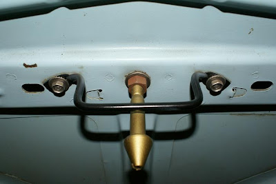
Here's how you adjust your trunk lid so that you don't have to slam it shut, or have it rattling and bouncing around, or have your trunk fill up with water every time that it rains. The first picture shows the bolts that hold the trunk lid catch to the car. If you have to slam the trunk shut to get it to catch, you simply loosen these two bolts and raise the thing up a hair. Close the trunk and see what it feels like, and tweek as needed to get it to close correctly. Be careful when you close it the first time, because the catch might have scooted over a little bit to one side, causing it to push the trunk lid over a little bit, which, in turn, causes the trunk lid to hit the rear quarter panel and chip your paint.
If your trunk lid is alligned a little bit funny, like sitting too far up in the back or is a little bit cockeyed, this, also, is not a big deal at all. To get the trunk lid to drop down in the back, loosen the bolts shown in the second picture on both sides of the car and let the trunk lid drop a little bit, snug up the bolts, close the trunk lid and tweek as needed. If the trunk lid is sitting a little bit too far forward (towards the rear of the car) you just loosen the four bolts that hold the trunk lid to the hinges and adjust accordingly. Be careful not to have it too far back because the back edge of the trunk lid could hit the panel that's right in front of it and chip your paint. These are very easy adjustments to make, and your car will really appreciate it if you stop all of that water from gushing into the trunk and quit slamming the trunk lid shut.

Thursday, April 17, 2008

Mustang Brake lights 1965 and 1966


Here is a diagram of how the brake lights work on your car. If you click on the diagram, you will then be able to see the entire diagram, instead of just the left half that you see now. I made the diagram as big as possible so that it would be easier to see. Now,moving back to how the brake lights work, there are actually two different circuits. The bulb in the tail light socket is a dual filament bulb. Power comes from the headlight switch over to the brake light switch, which breaks the circuit. When you step on the brakes, that completes the circuit in the switch, and power then proceeds from there to the turn signal switch, which sends the power on back to the tail light sockets, lighting up the brighter of the two filaments in each of the tail light bulbs. When the tail lights are not on, and you have your foot on the brake pedal, both of the brighter filaments should be on, until you activate the turn signals. Then one bulb stays light and other blinks full on/all the way off. When the tail lights are on, like when driving at night, that activates the dimmer of the two filaments in each bulb. When you step on the brake pedal, again, both bulbs are full on. When you signal a turn, one bulb will be full on and the other will blink full on/ half on, because one filament is still getting power as a tail light from the headlight switch.
The most common problems with the brake lights make up a pretty short list. At the top of that list is the bulbs are burned out in the tail lights. Always check that first. Then, it would be the plug-in connector to the tail light housing, or the socket on the housing itself, has gotten all corroded and funky looking. After that would be the brake light switch ( part # C5AB-13480-C) has gone bad. Replacing this isn't a big deal at all. It's hanging on the brake pedal arm, up above the steering column. You just unplug the two-wire connector, remove that pin that goes through the peg that the switch and the master cylinder push rod are hanging onto, pop the master cylinder push rod off of the peg and the switch will fall out into your hand. Nothing to it. On an earlier car ( like mine) the brake light switch is screwed into the front of the master cylinder, but the wiring system is the same. The only difference is the actual location of the brake light switch. Sometimes, the turn signal switch is the culprit, but normally a bad turn signal switch will make your car go retarded on you in some other way. Occassionaly it will be a problem with the wiring or the head light switch, which is the source of power for the brake lights.
How to trouble shoot the brake lights should go like this. First, check the bulbs and the sockets in the tail lights. Next, unplug the connector from the brake light switch and take a paper clip, bend it in such a way that you can stick that into both slots of the wire connector. Try not to have your skin touching any bare metal on the car when you do this, as it might deliver a little bit of a shock to you. It isn't dangerous, but it also isn't very enjoyable. If the brake lights come on, replace the brake light switch. If the brake lights don't come on, check with a volt meter to see if power is reaching the connector. If no, find out why not by checking the headight switch and connector. The wire that supplies power to the brake lights is coming out of the same slot in headlight switch connector that has the big yellow wire that supplies power to the horns. If yes to power reaching the brake light switch connector, check with the volt meter to see if power is leaving the turn signal switch at the two wire connector coming out of the steering column from the turn signal switch. If yes, your problem is in the wiring along the tail light harness somewhere. If no, your problem is in the turn signal switch, or the wiring going to or from it. Problems with this system, just like any other, are diagnosed by starting at one end and systematically going through the circuit until you find the break. You can do this.

Friday, April 11, 2008

1965 1966 Mustang Instrument Cluster Removal


There are many things that a person might need to do to their car which are very simple tasks with the instrument cluster removed and are virtually impossible with the instrument cluster still in the car, such as replace the headlight switch or replace one or more of the light bulbs back there. Removing the entire cluster can seem like a scary proposition if you are unfamiliar with how all of that junk back there goes together, but it is not a big deal at all.

First, disconnect the negative battery cable from the battery. Next, you have to disconnect the speedo cable. There is only one route that your hand can take to reach it. With the driver's side door open and you on your knees outside of the car, you have to run your hand up between the emergency brake handle and the air vent cable. From there, you keep running your hand up until you locate the speedo cable. Where the speedo cable goes into the back of the instrument cluster there will be either a round, gnurled knob thingy or what feels like a big hex nut. Either way, you just unscrew that and pull the cable out of the back of the speedometer. It might be a little snug, but fortunately, there was no way for the last owner to get a wrench on that, or tack weld it in place, so you will be able to unscrew it by hand. I don't have any trouble at all getting my hand up there, but men sometimes find that their forearm is just a tad too big to squeeze in there. If this is the case, just take those two big screws out that are holding the emergency brake handle assembly and the air vent knob to the dash and that will give you enough room.

Once you have the speedo cable loose, remove the six screws that hold the instrument cluster to the dash. There are four along the top and two on the bottom. Work the instrument cluster out far enough to start unhooking all of that stuff back there. The wires just unplug and the bulb sockets just pull out. Once you have every thing unhooked, remove the instrument cluster from the car. Be sure and have a towel or something on the steering column because you will definitely scrape up the paint if you don't. The second picture is color-keyed to show you how the wires and bulbs go back on. There will also be an instrument cluster voltage regulator with three wires attached to it. Two of them will be dark green with a black stripe, and one will be black. How this works is in the section on gauges, along with the wiring diagram, but, the black one is the dash ground and the two green with black stripe are power-in / power-out for the instrument cluster voltage regulator. The third picture is to show you exactly where the speedo cable is attached to the instrument cluster.

This has all been for either a 66 model car, or a 65 that that has gauges instead of idiot lights. A 65 with idiot lights is just like a 66, except for you just unplug the lights instead of some wires. On some, you have to twist the idiot light sockets and then pull, and on some you have to just pull the bulbs out. On a 65 with gauges, there will be a big wire going through a loop on the back of the ammeter gauge. The wire has a disconnect that you can unplug several inches back from the gauge. When you run the wire back through the loop to re-install the instrument cluster, be sure that it goes through the same way it came out or your ammeter gauge will read backwards.

When you re-install the instrument cluster, it is very good idea to hook everything back up except the speedo cable and, before you put the six screws back in, re-connect the battery and check to see if everything works like it's supposed to, so that, when you hit the left turn signal, your high beam indicator isn't the one that starts blinking. It is also a very good idea to, while you have the instrument cluster out, replace all of the bulbs. They are available at any auto parts store and are cheap. The part number for the bulbs is 1895. Nothing to it.

Tuesday, April 8, 2008

1965 and 1966 Mustang hood adjustment


It is very common to see an otherwise beautiful car that has the hood sitting on it a little funny. Trying to adjust that can be very annoying if you aren't really sure what's making it do that. Fortunately, it's a very simple matter to correct. The second picture shows the hood latch stuff that's mounted on the hood itself. Remove that by loosening the nut that locks the hood stob into place, unscrew the hood stob and then remove the safety catch by removing the two bolts. Loosen the four bolts holding the hood onto the hinges a couple of turns, but DO NOT remove them. Close the hood very carefully, in case it has moved on you and could hit one of the fenders or the cowl panel and damage your paint. Once you have the hood stob and safety catch removed, the bolts loose and the hood closed, bump the hood around gently until it is sitting like it's supposed to, raise the hood very carefully, so that it doesn't shift on you, just high enough to get a half inch boxed end wrench on the front bolt of each hinge and snug them up enough to keep the hood from moving, raise the hood the rest of the way and tighten up the bolts. Be careful the first time that you raise the hood because it can look like you've got the perfect gap between the back edge of the hood and the cowl, but actually it's a little too close and the hood will hit the cowl on the way by as you open it and chip the paint. Also, be careful the first time that you close the hood after you tighten up the hinge bolts, because that might lower the back edge of the hood a little bit and, again, cause the hood to hit the cowl and chip the paint. Re-install the hood stob and safety catch.


Now that you have the hood sitting in the right spot, you need to make sure that the hood latch assembly, shown in the third picture, doesn't push the hood over to one side or the other when you close it, causing the hood to hit one of the fenders and, again, chip the paint. Loosen the bolts holding the hood latch to the hood latch bucket. On a 64 1/2 or a 65, there will be three bolts, on a 66 there will only be two. Lower the hood to where the hood stob is almost going into the hood latch and look to see if they are lined up correctly. The hood stob shouldn't be trying to push the hood latch one way or the other. Bump the hood latch around until it looks like the stob will go in without actually touching the latch at all, and then tighten up the bolts holding the latch. Close the hood carefully to make sure that nothing is hitting something else.

Now it's time to adjust the hood stob. With the hood fully closed and latched, the hood shouldn't be able to bounce up and down, but you also shouldn't be have to slam the hood closed to get it to latch. Screw the latch stob up or down as necessary to make this happen. You should be able to hold the latch release handle open with one hand, close the hood with the other, release the handle, and the hood is fully latched but won't move up or down when you try to wiggle it. Once you have the latch stob positioned like it needs to be for this to be the case, tighten up the lock nut on the latch stob.
In the first picture you see one of the two adjustable hood bumpers that control how far down the front of the hood is able to come. These are adjusted by loosening the nut, indicated by the red arrow, and then screwing the bumper up or down as necessary. When the hood is pressing lightly agianst the bumbers so that it can't go down any further, and the latch stob is fully latched, preventing it from moving up any further, but you didn't have to slam the hood shut to get it to 'catch' , that is how the hood is supposed to be at the front end.


If you look at the fourth picture, you will see that the hood is centered well, but is sitting up too high in the back. The fix for this is NOT to lean on the area until the hood goes down to flush with the fender. This is adjusted by opening the hood, loosening the three bolts holding the hinge to the car on both sides a couple of turns and pushing up on the front of the hood, causing the back of the hood to rotate downward. Be careful that the entire hinge doesn't drop down on you. How I do this is to leave the lower front bolt on each hinge sort of tight. I just kind of break it loose with the wrench, but leave it very snug. That way, the hinge rotates rather than drops. I normally use a telescoping hood prop to push the front of the hood up and hold it there, but I have found that a conveniently located friend works just as well. She holds the hood up while I snug the bolts back up. Close the hood carefully to make sure nothing hits anything and then tweek as needed, and then your hood sits in there perfectly.

Wing window adjustment


The wing window being slightly out of adjustment is a fairly common cause of having the door window not operate as smoothly as it should, the reason for this being that the front edge of the door window rides inside the track on the wing window assembly. When this is running a little bit off from the how the rear door window track runs, it causes the window to bind up a little bit. Adjusting the angle of the wing window is very simple. In the first picture you see the entire assembly. On the left hand side of the picture there is a leg sticking downward that is chromed. That leg will have two funny looking bolts holding it onto the door. You remove the top one and loosen up the bottom one. If you look at the second picture, you can see how the adjustments are made with the funny looking bolt.The flat part on top of the bolt is behind the attaching point and the lock nut is attached out in front of the attaching point. You take an allen wrench run the bolt in or out to position the top end of the window like it needs to be, and then use the same procedure to adjust the angle that the window sits at with the adjusting bolt that is in the bottom end of the long track on the right hand side of the assembly, as shown in the last picture. Then sng up the nut that holds the attaching bolts in place, and there you are. Nothing to it.

Monday, April 7, 2008

1965 and 1966 Mustang door window adjustment


To adjust how far up or down the door window is able to travel, you simply loosen the two bolts shown in the first picture, roll the window up to where it should stop, position the window stop against the regulator arm, tighten that bolt up, roll the window down to where it should stop, position the other stop where it needs to be, and tighten that bolt, and then roll the window all the up and VERY CAREFULLY close the door to make sure that the window isn't going to hit anything as you close the door. Tweek as needed to make the door window stop exactly where you want it to.

If the window seems to be binding and it is very difficult to roll up or down, this is very often a mis-alignment of the two guide tracks that the window rides around in. Those two tracks have to be parallel for the window to operate smoothly. The rear track, shown in the second picture, is adjusted by loosening the two bolts that are up near the top and the nut that is down near the bottom. If you open the car door and look at the face that the door latch sticks through, you will see two bolt heads up near the top door face plug and the upper door bumper. Those are the guide track bolts. If you remove the lower door face plug, inside that hole you will see the nut. Loosen those, roll the window all the down, wiggle that guide track around until it is in a relaxed position, and then snug everything back up. If this fixes the problem, cool. If it fixes the problem, but now the angle of the window is off when the window is rolled up all the way, as in, it's leaning outward or inward too far, then tou will need to adjust the front track, which is part of the wing window assembly, and then repeat the process for adjusting the rear track. The reason that you should start by trying to adjust the rear track first is because this does not require removing the door panel. A really tight window can also be caused by a bad window regulator or possibly something as simple as the scissor guide tracks needing a touch of grease. These are not parts that generally receive regular lubrication. Do NOT lubricate the window guide tracks. Whatever you use to lubricate these tracks will get on the glass itself, and look just terrible. The wing window adjustment procedure will be in a section of its own.

Sunday, April 6, 2008

Door window regulator assembly

Are you tired of having to lift up on the back of the window in order to roll the window down? This first picture is what your window would look like rolled down inside the door if you car had the rare invisible door option. How your window regulator mechanism works is the two upper arms of the regulator scissors are attached to the track on the lower part of the window frame and the third, lower arm is attached to a short piece of that same frame stock that is held onto the inside part of the door itself with two bolts. When you turn the window crank, the other end of the piece that the window crank handle is attached to has gear teeth, which mesh with the saw-blade looking part of that big flat piece on the regulator that has the big watch spring thingy on it. The spring is designed to help lift the window and apply a bit of resistance to lowering the window, so that it takes about the same amount of force to lower it as it does to raise it, and to hold the window up. Without the push from that spring, the window would just drop down into the door. As that big flat piece rotates around, it pushes or pulls on the regulator arm, which , in turn, pushes or pulls on the regulator scissors. The scissors bracket is held to the door with three bolts. The black part of the scissors work like a bell crank and push the window up or pull it down when the regulator arm moves. The next two pictures show how the regulator arm is attached to the scissors. There is a little post on the scissors and a hole in the end of the regulator arm. The post goes through the hole and then a clip is installed to hold them together.


If you have to lift up on the back of the window to lower the window, or it acts like one end of the window is trying to outrun the other, what has probably happened is that one of the scissors arms has popped loose from the roller that holds it into the track. The fourth picture here is one of the scissors arms with the roller attached to it. The next picture is of the roller itself and the clip that holds it onto the scissors. You just place the roller onto the scissors arm and install the clip and that holds the roller on. There is a groove in the roller that holds it onto the track.

To replace the window regulator you have the window in the up position, stick something like a piece of wood underneath the window to hold it up, unhook the clip from the end of the scissors , pop the regulator arm loose, remove the four bolts that hold the regulator onto the door and remove the regulator from the door. To install the new regulator, just do what you just did backwards. Don't lose one of the bolts that hold the regulator on. They're really short like that for a reason. It's so that the saw blade piece of the regulator doesn't hit them and get jammed up on the way by.
To replace the scissors, you again have the window all the way up with a piece of wood under it to hold it there, remove the clip and pop the regulator arm loose from the scissors, remove the clips from the three rollers, pull the scissors arms out of the rollers, remove the three bolts holding the scissors bracket to the car, and remove the scissors from the door. Again, installation of the new one is do what you just did backwards.

Friday, April 4, 2008

Mustang door lock, latch and handles 1965 1966


Here is how the door latch, release handles and locks work on your car. In the second picture, the outside door handle rod is indicated by the green arrow, the rod that the door lock knob screws onto is indicated by the blue arrow, the outside door lock cylinder rod is indicated by the red arrow, and the inside door release handle rod is indicated by the brown arrow. The third picture ( further down )shows how the outside door handle rod is connected to the latch mechanism in the red circle. It is basically just pushed into a slotted plastic bushing. You don't want to detach that if you don't have to because they never really hold as well after they've been popped loose and then reinstalled. The outside door lock cylinder rod is held to the latch by a springy little clip, as shown in the green circle. If you look at the fourth picture, you will have a much better look at another one of those clips which is holding the outside door handle rod to the outside door handle. The clip has been popped loose, which allows the rod to be removed from the handle.
If you are replacing the outside door handle, you just pop that clip loose, remove the nut that's holding the front of the door handle to the car, and then the phillips head screw that's holding the rear part of the door handle to the car. If you open the door and look at the face where the latch sticks out , where the door tag is on the driver's side door, etc.. you will see two rubber bumpers, or possibly just the rectangular holes where the bumpers are supposed to be. About four inches above the top bumper is a screw head. That's the one holding the door handle.
The next picture shows the outside door lock cylinder attached to the rod, again, with one of those clips. And, again, the clip is popped loose. To remove the lock cylinder, you simply pop that clip loose, and then pull the big, flat U-shaped clip that's holding the lock cylinder onto the car, as shown in the top picture, along with the part number for a new lock cylinder set, and then carefully pull the old lock cylinder out of the door from the outside. It is very, very easy to damage your paint when removing the door handle and the lock cylinder. Just take your time, be careful and you shouldn't have any problems.
The last two pictures show the attaching points for the inside door release handle rod. The last picture shows the rod attached to the door release lever mechanism. This triangular shaped piece is what has the shaft that the inside door release handle is attached to. That shaft is over on the other side of piece. The next to the last picture shows the inside door handle release rod attached to the door latch mechanism, again, with one of those clips.
Just a word about those clips. They have a death-grip on those rods. It would be very impressive indeed to see someone just reach in there and pop them loose with their fingers without gashing those fingers to shreds in the process. I take a very small flat blade screwdriver and push up under that little tail on the clips and pop them loose like that. Also, I never had any trouble reaching any of this stuff inside the door, but, if you are a man, your arms will be several inches longer and significantly larger in diameter than mine. At least, I would certainly hope that they are. (I wish I had smilies here) Also, you have the window regulator mechanism and the rear guide track for the window to work around. With all of this stuff still inside the door, you can't actually see most of this junk while you're working on it. You have to do it by feel, using the three-dimensional hologram diagram in your mind as a guide. Also, you can't possibly get both hands on the same component at the same time. You locate the rod, feel along to the end until you locate the clip, feel for the little tail on the clip and which way it's pointing, put the little screwdriver under it and pop it loose.
Once you get to this point, if you want to actually remove the latch mechanism, all you have to do is remove those three phillips head screws holding it onto the car that are located on the outside of the door latch, forming a little triangle around the latch, and then snatch it out of there. The window's rear guide track is going to try to prevent you from removing the latch mechanism, but don't take no for an answer. It's your car, not the guide track's.